The Farthest Shore – Chapter Nine Space Missions and Programs
From The Space Library
Chapter Nine Space Missions and Programs – Why and How We Go to Space
Angie Bukley, Eric Choi, John Connolly, Arthur Guest, Linshu He and Kazuya Yoshida
“Ships and sails proper for the heavenly air should be fashioned. Then there will also be people, who do not shrink from the dreary vastness of space.” -- Johannes Kepler, 1609 † Unless otherwise indicated, the authors developed the graphics for this chapter.
Engineering space missions require that we look beyond only spacecraft and their associated subsystems discussed in the previous chapter. Space mission designers also need to know about astrodynamics, launch vehicles and mission operations that are covered in this chapter. Most importantly, this chapter will examine how all these pieces fit together to form working “systems” to support space missions and programs.
9.1 Space Missions
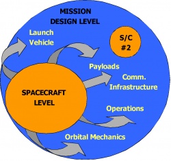
A spacecraft alone cannot perform a space mission. It must be combined with a launch vehicle, payloads, communication and navigation infrastructure, mission operations, and an understanding of orbital dynamics to assemble a working space mission.[1]The second shell of the three-level model introduced earlier illustrates how the spacecraft exists as a component of the overall mission, as shown in Figure 9.1. Space missions may also involve other specialties such as other cooperating and supporting spacecraft, human crewmembers, ground command, testing and processing facilities, and planetary astrodynamics.
As was the case with the design of the individual spacecraft, an expert Mission Designer who understands each of the above specialties as well as the interconnections among them must make difficult choices. Those in charge of the mission must choreograph the design of the overall space mission. Mission designers must also understand how the choices they make in mission performance affect the costs, the risks, and the mission goals and objectives. Missions are rarely flown because they are the lowest cost, or the lowest risk, or the best performance. Experienced designers and managers will choose mission designs that often have the best balance among all three of these prime factors.
It is hard, for instance, to purchase a new luxury automobile at the price you would expect to pay for an older, used car. Further, it would be unlikely that the older, used car would be as reliable as the new automobile, and the risk of the older car requiring maintenance would be much higher. Mission designers similarly need to make tradeoffs and seek the best over-all result based on those “balanced decisions.”
†9.2 Just what is an Orbit? Astrodynamics 101
We have already discussed spacecraft orbits and introduced the idea of LEO, MEO and GEO orbits back in Chapter 6. We now want to go back and explain the physics behind these orbits, and indeed the planets and their various moons as well.[2]
Let’s begin with some history. Astrodynamics is the branch of engineering related to the motion of natural and artificial objects (satellites) in space. It is a subject that some people find difficult and intimidating, but this should not be the case. The basic concepts of astrodynamics are quite straightforward, and the subject has a very rich and fascinating historical foundation.
For much of recorded human history, it was believed that the other planets revolved around the Earth. This geocentric (“Earth-centered”) model of the solar system is commonly attributed to the Egyptian astronomer and mathematician Ptolemy (87–150 AD). In Ptolemy’s elaborate model, the planets moved about in small circles called epicycles. Under this theory the centers of these epicycles moved around the Earth in perfect circles called deferents. This system was used for 1400 years and was considered a true interpretation of planetary motion. The Ptolemaic system was useful in at least describing the motions of the planets as seen from Earth.
In 1543, the Polish astronomer Nicolaus Copernicus (1473–1543) broke with Ptolemy’s theory and advocated a heliocentric (“Sun-centered”) model of the solar system. Mathematically, the heliocentric model is simpler than the geocentric one and it explained better many astronomical observations like the “retrograde motion” of Mars. By the principle of Occam’s razor, if two theories explain the observations equally well the simpler theory is more likely to be true. However, acceptance of the heliocentric model was slow because at first it did not seem to explain the observations any better than the geocentric model. This was because of the measurement errors inherent in the naked eye measurements of the day. In addition, the Copernican model still had the planets orbiting in perfect circles, mostly for philosophical and religious reasons, which was later shown to be incorrect.
Much of the foundation of astrodynamics can be credited to the Danish nobleman and astronomer Tycho Brahe (1546–1601). While a student, he lost part of his nose in a drunken sword fight, and wore a prosthetic nose for the rest of his life. Tycho Brahe did not support Copernicus’ heliocentric model of the solar system, but he was open-minded and was deter-mined to catalogue the planets with enough accuracy to determine which of the two competing theories was correct. From the observatory in his castle, he collected very accurate observations of planetary motion over the span of 20 years. Of equal importance to the observations themselves was the fact that Tycho Brahe recorded the measurement errors associated with the data. This would eventually become standard scientific practice, but it was revolutionary at the time. His achievement is all the more remarkable considering it was done without the use of a telescope. He could not explain his observations mathematically, but his apprentice, Johannes Kepler, would eventually accomplish this.
9.2.1 Kepler’s Law
Upon Tycho Brahe’s death in 1601, the German astronomer and mathematician Johannes Kepler (1571–1630) inherited his mentor’s job and, more importantly, his astronomical data. Kepler analyzed Brahe’s observations to look for patterns, with emphasis on trying to mathematically explain the orbit of the planet Mars. Like Copernicus before him, Kepler originally believed the orbits of the planets to be perfect circles, again because of the philosophical and religious notions of the day. But there was no way Kepler could fit Brahe’s data to a perfect circle, and thanks to Brahe’s meticulous recording of observational errors he knew the data was accurate. Eventually, Kepler concluded that the orbits of Mars and the other planets are ellipses , not circles. It was a triumph of the scientific method, in which a preconceived belief, however appealing, must yield to empirical evidence.
Around 1605, Kepler presented his three laws of planetary motion . These laws form the basis of our understanding of satellite and planetary motion.
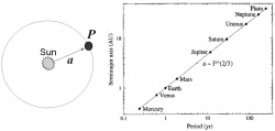
- Kepler’s First Law – The orbit of each planet is an ellipse, with the Sun at one focus as shown in Figure 9.2.
- Kepler’s Second Law – A line that joins a planet to the Sun sweeps out equal areas in equal times, as shown in Figure 9.3. For satellites in Earth orbit, Kepler’s Second Law could be restated as follows: “A satellite orbits such that the line joining it to the center of the Earth sweeps over equal areas in equal time intervals.” In other words, a satellite moves faster when it is close to the Earth and more slowly when it is further away. This is an illustration of a principle called conservation of angular momentum , which will be discussed later.
- Kepler’s Third Law – The square of the period of a planet’s orbit (P ) is proportional to the cube of its mean distance from the Sun (a ). In other words, the further a planet is from the Sun (or the higher a satellite is from the surface of the Earth), the longer it takes to move along that part of the orbit. This is illustrated in Figure 9.4.
9.2.2 Classical Mechanics and Newton’s Law
While Kepler’s Laws describe planetary motion, it was the English mathematician and physicist Sir Isaac Newton (1642–1727) who would discover the underlying physics behind the observed motion. Newton’s most famous book was called Philosophiae Naturalis Principia Mathematica , more commonly known as simply the Principia . This incredible book transformed the world’s understanding of almost everything—starting with gravity. This amazing work was published in 1687 and contained his Three Laws of Motion. This is the basis of what is now known as “Newtonian” or “classical” mechanics.
Before discussing Newton’s Laws, two basic terms need to be defined: mass and inertia . In everyday conversation, the words “mass” and “weight” are often used interchangeably, but in fact they are quite different. Mass is the quantity of matter in an object, whereas weight is the force that gravity exerts on a mass. This means that if you were to go to the Moon or another planet in the solar system, your weight would change but your mass would remain the same.
The Italian scientist Galileo Galilei (1564–1642) was the first to define inertia as “the tendency of an object to stay at rest or stay in motion unless acted on by an outside force.” In other words, unless some outside influence forces a change, objects will tend to keep doing what they are already doing. The amount of inertia an object has is related to its mass. A massive object like an ocean liner has lots of inertia, so a large force is required to change its motion, while a far less massive object like a sailboat has little inertia and can be moved with little force.
Newton’s Laws of Motion are as follows:
- Newton’s First Law – An object at rest will tend to stay at rest, and an object in motion will tend to keep moving in a straight line, unless acted upon by some outside force.
- Newton’s Second Law – The acceleration of an object is proportional to the force applied, and is in the same direction as that force.
- Newton’s Third Law – For every action there is an equal and opposite reaction.
The latter is probably the best known of Newton’s three laws, and is really what makes spaceflight possible. A spacecraft is fixed to a rocket engine that propels exhaust gases out the back. Because every action has an equal and opposite reaction, the spacecraft is propelled forward. Newton’s Third Law is an expression of a physical principle known as the conservation of momentum . Momentum is the “quantity of motion” that an object has. Linear momentum is the quantity of motion in non-spinning objects, while angular momentum is the quantity for an object that is spinning or revolving about another object.
Linear momentum is defined mathematically as the product of mass and velocity. If there are no external forces acting on a system, its total linear momentum does not change. This is called the conservation of linear momentum. The recoil of a cannon is an example of this phenomenon. Before the cannon is fired both it and the ball are at rest, so the total linear momentum is zero. Upon firing, the ball shoots out at some velocity. For the system to maintain a net linear momentum of zero the cannon must go in the opposite direction at its own velocity to compensate, i.e. it recoils.
Angular momentum is defined mathematically as the product of angular velocity (the speed of rotation) and a quantity called moment of inertia . Moment of inertia is the rotational analog of mass. It is measured with respect to an axis of rotation and depends on the shape of an object and the distribution of its mass about that spin axis. Mathematically, moment of inertia is calculated by multiplying the mass by the square of its radius from the spin axis. If there is more than one mass, these terms are added up to form the total moment of inertia about that axis. The greater the radius or the larger the mass, the greater is the moment of inertia about that axis. Just as it takes more force to start or stop moving an object having a large mass, it requires a lot of torque to start or stop the spinning of a body with a large moment of inertia.
If no external torques act on a system, total angular momentum remains unchanged. Think of an Olympic figure skater spinning on the toes of her skates as an example of the conservation of angular momentum . Once she starts spinning, she has a certain amount of angular momentum. When she puts her arms out sideways, the distribution of mass has changed such that the moment of inertia (normally denoted as I ) increases. Because the total angular momentum must be conserved, the spin rate (normally denoted as ω) must therefore decrease. The opposite occurs when the skater pulls her arms in. Mass is now distributed closer to the spin axis, so the moment of inertia I decreases. To keep the same angular momentum, the spin rate (or angular velocity) ω goes up to compensate, and she spins much faster.
Along with being the primary way in which attitude control of a satellite is accomplished, as discussed previously, conservation of angular momentum is the physical basis behind Kepler’s Second Law of planetary motion. The speed of a satellite in Earth orbit (or of a planet in orbit around the Sun) varies in manner similar to that of the spinning figure skater in the previous example. A satellite’s speed is greatest at perigee , when it is closest to the Earth, and is slowest at apogee , the furthest point in its orbit from the Earth.
9.2.3 Universal Gravitation and the Basic Principles of Orbit
Why doesn’t the Moon fall out of the sky, the way the apple fell out of the tree and hit Isaac Newton on the head? The answer is…the Moon actually is falling! Imagine firing cannon balls from the top of a hypothetical “extremely high” mountain as shown in Figure 9.5. According to Newton’s First Law, if there were no external forces, the cannon balls would just keep going in a straight line. But in this case, there is an external force – gravity. The Earth’s gravity (actually air resistance too, but we will blithely ignore that) would bend the path of the cannon ball and cause it to fall back to Earth (1). The faster the cannonball is fired, the farther it goes before falling back to Earth (2). If the cannonball is going fast enough, it will not hit the surface because the Earth is curving away from the cannonball at the same rate as the cannonball is falling. Like the Moon, the cannon ball would be in orbit around the Earth (3).
The key point here is that velocity in a particular gravitation field determines the characteristics of the orbit . If you remember this key point and understand the concept of the mountain and cannon balls diagram, you already understand most of the theory behind astrodynamics.
According to Newton’s Law of Universal Gravitation , the force of gravitational attraction between any two objects (such as a cannon ball and the Earth) is directly proportional to the product of their masses and is inversely proportional to the square of the distance between their centers. The more massive the objects and/or the closer they are together, the greater the force of gravitational attraction between them. This law is called “universal” because as far as we know the same principle applies everywhere in the Universe. The motion resulting from this gravitational attraction is called two-body motion .
In two-body motion, the shape of an orbit is determined by the speed at which the object is moving. The “slowest” launch produces a circular orbit, because this is the simplest shape that can be achieved without the object crashing back to Earth. As the launch speed increases, the orbit becomes more and more elliptical, or eccentric . Parabolas and hyperbolas are fully open trajectories that result when the object is launched so fast that it “escapes” the gravity of the planet. These four types of orbits – circle, ellipse, parabola and hyperbola – are called conic sections because they are produced when a circular cone is sliced at various angles.
9.2.4 Describing an Orbit
Recall from the previous chapter that there are exactly six parameters (or degrees of freedom) required completely and unambiguously to describe the position and orientation of any object in space – three fixing positions in three-dimensional space (3D), (x, y, z), and three describing attitude (roll -φ, pitch -θ, yaw -ψ). The most common notation for describing satellite orbits uses Keplerian or “classical” orbital elements , which define the following:
- The size of the orbit
- The shape of the orbit
- The attitude of the orbit (tilt, orientation and rotation)
- The location of the satellite in the orbit.
These orbital elements, together with a time stamp (or epoch), make up a state vector , which is simply a set of parameters (numbers), which describes the location of a satellite in space at a specific instant in time. The six Keplerian orbital elements are summarized in Table 9.1.
9.2.5 Orbital Perturbation
In the real world, satellite orbits around the Earth (or other heavenly bodies for that matter) are not the perfect conic sections dictated by Newtonian two-body motion. This is because they experience orbital perturbations, or disturbances, which result from a variety of external forces. The major perturbation forces are:
- Atmospheric drag
- The Earth’s equatorial bulge, or oblatene
- The Earth’s triaxiality, or non-spherical equator
- Third-body effects from the gravitational attraction of the Sun, the Moon and other planets in the solar system
- Solar radiation pressure
- Unexpected thrusting, either from out-gassing or erroneous thruster activity.
For Low Earth Orbit satellites, atmospheric drag and the Earth’s mid drift bulge are key factors. These are lesser factors for orbits that are further from the Earth, such as GEO orbits that are nearly a tenth of the way to the Moon.
9.2.6 Types of Earth Orbit
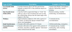
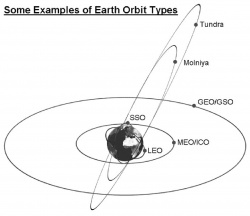
Table 9.2 summarizes the various orbits and their primary usage. Figure 9.6 shows, not quite to scale, the relative spacing of these orbits in relation to the Earth. It is clear that the orbital characteristics, the sizes of the gravitational forces acting on the satellites, and virtually all of the orbital state vectors are quite different for the satellites in these different orbits.
9.2.7 Maneuvering in Space
On nearly every space mission, it is necessary to change, or adjust, the orbit by making orbital maneuvers. There are several reasons for making orbital changes, including the following:
- When a satellite is launched, it is usually not deployed directly into its final orbit.
- The satellite’s orbit must be maintained against orbital perturbations, especially atmospheric drag for satellites in Low Earth Orbit and for gravitational effects of the Moon and the Sun for GEO orbits.
- The satellite may need to be sent to a new orbit in order to accomplish its mission.
As we have previously discussed, velocity determines the characteristics of the orbit; therefore, changing the orbit requires changing the satellite’s velocity. For this reason, an orbital maneuver is often called a delta-V (ΔV). The Greek letter “delta”, or ∆, is used in mathematics to indicate a “change.”So ΔV denotes a change in velocity V. If the velocity is increased along the direction of flight, the altitude is raised. The orbital period lengthens, and by Kepler’s Laws the satellite “falls behind” satellites in lower orbits. Similarly, a velocity decrease reduces the satellite’s altitude. The period gets shorter and the satellite “pulls ahead” of satellites in higher orbits. To change the apogee (highest point) of the orbit, the satellite must change its velocity at perigee. On the other hand, to change perigee (lowest point in the orbit) the satellite must change its velocity at apogee. Out-of-plane maneuvers are those that change the orientation of the orbit, thus altering the inclination. To change the inclination only, the spacecraft’s thrusters must be fired at either the ascending or descending node. Firing the thrusters at any other point in a generic orbit alters both the inclination and the ascending node. GEO satellites must maintain their inclination to minimize their North-South drift. Out-of-plane maneuvers require a tremendous amount of energy because of the high velocities involved.
It is often necessary to move a satellite from one orbit to another. The most fuel-efficient method of doing this is called the Hohmann transfer , which consists of two separate thruster firings as shown in Figure 9.7. At maneuver point 1, the spacecraft fires thrusters to increase velocity and move from the initial orbit into a transfer orbit. At maneuver point 2, on the opposite side of the Earth, a second firing again increases the velocity for insertion into the target orbit. This is sometimes called the circularization burn because the target orbit must be less eccentric than the transfer orbit. If the circularization burn does not occur, perhaps due to a malfunction, the spacecraft gets stuck in the transfer orbit.
9.2.8 Interplanetary Travel
The Hohmann method is the most fuel-efficient technique for interplanetary transfer to leave the Earth’s gravity and go to other planets in the solar system. As an example, consider a Hohmann interplanetary transfer for sending a spacecraft from Earth to Mars. To achieve the transfer, the Earth at launch and Mars at arrival must be directly opposed. The launch must be timed so that the transfer trajectory takes the spacecraft to the point where Mars will have “caught up” by the time of arrival. For Earth-Mars transfers, this optimum alignment occurs every 26 months. This period defines the launch opportunity . Launching at other times requires greatly increased fuel consumption, or it may be impossible to achieve the mission with current propulsion technology.
However, using the Hohmann transfer to reach other planets generally takes a long time. For example, it would take 40 years for a spacecraft to reach Pluto using a Hohmann trajectory. Faster, non-Hohmann trajectories are possible, but these require either a tremendous amount of chemical fuel or entirely different technologies, such as the use of solar sails or nuclear energy. Another approach is for the spacecraft to get a “slingshot” boost through a “gravity assist” maneuver, in which the gravitational field of a planet or the Sun is used to change the spacecraft’s velocity (its speed and direction) while en route to another planet.
Changing the velocity of a spacecraft through gravity assist is called “pumping”. When a spacecraft passes close to a planet or the Sun, it is pulled towards it by gravity and its velocity increases. If it passes “behind”, as shown in the diagram of Figure 9.8a, without the gravity assist the spacecraft would continue following the dotted trajectory. But thanks to its encounter with the planet, the trajectory has been “bent” so that, in effect, its velocity has increased with respect to the Sun. Gravity assist can also be used to decrease velocity, as illustrated in the diagram in Figure 9.8b. If the spacecraft passes “inside” or “in front” of a planet, it is pulled against its direction of flight, decreasing its velocity with respect to the Sun. Mariner 10 mission planners were the first to use this technique in 1974. In this case a gravity assist maneuver at Venus was used to slow the spacecraft towards a rendezvous with Mercury.
9.3 Getting There – Let’s take a Rocket Ride!
Getting the spacecraft into orbit is accomplished with a space launch system or rocket. Once in orbit, the spacecraft may be required to perform maneuvers like attitude changes, or even change orbits as was just discussed. Sometimes, as in the case for interplanetary spacecraft, the vehicle must propel itself out of Earth orbit and on to its final destination. To accomplish this, space propulsion systems are employed. [3] Space propulsion is defined as a class of propulsion that produces a propulsive force in (empty) space using Newton’s Third law of Motion. Space Propulsion systems include chemical and nuclear rocket propulsion, and solar sails. It excludes those means of propulsion that require:
- air to provide the propulsive force, e.g., an air-breathing jet engine, and
- direct contact with the Earth, like wheeled or tracked propulsion.
Space propulsion is needed to do many things including[4]
- Launch a space vehicle from the earth,
- Accelerate a spacecraft to a velocity that will take it from one orbit to another (depending on the velocity, the spacecraft will either remain within the influence of Earth’s gravity or go beyond its influence, on to a distant planet, or even beyond the influence of the Sun and into interstellar space),
- Land or launch a space vehicle on a moon or planet
- Compensate for the influence of disturbing forces like drag, solar wind, or gravity (e.g., due to the dynamics of a rotating, non-spherical Earth) on the orbit or trajectory,
- Control the attitude of the vehicle (e.g., to orient antennas or sensors, or thermal control surfaces) or to compensate for disturbing torques.
Other functions that are accomplished using space propulsion include controlling the spin-up or spin-down of spacecraft, “unloading” reaction or momentum wheels on a satellite, separating vehicle stages, or settling propellants (sometimes required by liquid propellant systems).
Most spacecraft (including space launchers, satellites, space probes, and human-crewed systems) are currently propelled by accelerating and expelling mass from within the spacecraft in a direction opposite to the direction of travel. This is referred to as rocket propulsion. All the hardware and software needed to generate thrust is referred to as the propulsion system or subsystem. Most rocket propulsion uses chemical propellants both to generate the energy needed for thrust and as the mass expelled. Some spacecraft, such as the Pegasus rocket, the X-43 A and C hypersonic scram jet experimental planes and the now famous Spaceship One, use air-breathing propulsion for their lower stages. This has several advantages. The principal one is that there is no need to carry the oxidizer on the vehicle.
There are also incipient attempts to build a “space elevator” that could lift mass up to GEO orbit, and there have been a few experiments with “solar sail” systems. However, to date we remain heavily dependent on chemical rocket propulsion. In time this may well pass since chemical rockets are expensive, not all that “environmentally friendly”, difficult and expensive to build, and not the safest of vehicles.
Most satellites have simple and generally reliable chemical rocket thrusters to keep them in position, termed “station keeping”. Recently spacecraft and planetary probes have started to use non-chemical means, such as electrical rockets (e.g., ion rockets and “resistojets”) for some tasks.
Despite enhancements over the years, space propulsion systems are quite inefficient propositions. For instance, to put a 5 to 10-ton (5000 to 10,000 kilogram) payload into space, a giant space rocket, like the European Ariane 5 or Atlas 5, is needed. These rockets are essentially an empty tank that houses several rocket motors and the required propellant, which can be compared to the fuel for your car. The total mass of a fully fueled Ariane 5 rocket is over 746,000 kg, of which more than 80% (or 642,000 kg) is propellant. Given that it costs in the range of about €7,000-20,000 to launch one kilogram of mass into space, one can readily estimate the high cost of having to carry so much propellant along for the ride.
Space propulsion systems release tremendous amounts of energy over a short period of time, which sometimes leads to system failures. Investigations have shown that over 40% of all failures of space systems are due to the propulsion system failures. These are often a catastrophic failure, an explosion. They can also be a rocket engine that does not start, or an engine that does not function properly.
Before getting further into the details of propulsion systems, there is one term that requires a definition, as it describes how each is characterized; the term is specific impulse . Specific impulse, denoted I sp, is a rough measure of how fast the propellant is ejected out of the rocket nozzle. It is also a term that is used to describe the efficiency of the rocket. Specific impulse, given in seconds, represents the impulse, or change in momentum per unit of propellant consumed. The higher the specific impulse, the less propellant is needed to gain a specific amount of momentum, or to gain a certain increment of velocity. High I sp is good! Solid fuel rocket motors typically have a specific impulse around 250 seconds, while a bipropellant liquid fueled rocket might have a specific impulse of over 400 seconds.
9.3.1 Options for Space Propulsion
Space propulsion methods generally fall into one of two classes:
- Rocket propulsion wherein the propulsive force is generated by expelling mass (initially stored in the vehicle) from the vehicle, at a high velocity,
- Non-expulsion (non-rocket) propulsion through forces associated with the solar wind, a plasma beam, a magnetic field or the gravitational field of a celestial body.
Most rocket propulsion systems today are (thermo-) chemical or cold gas-based rocket systems, wherein the propellant both acts as the matter expelled and as the energy source needed to accelerate the expelled matter to a high velocity. They include liquid fuel, solid fuel, and hybrid rockets, and cold gas rockets.
In addition to these chemical systems, there are also non-chemical, or separately powered, rocket systems using nuclear and electrical power sources. The amount of power needed for thrust generation is so high, however, that such systems are limited to relatively modest thrust levels. In short, chemical rockets give you a short and highly energetic source of thrust. Nuclear and electrical systems give you much lower accelerative force but for much longer durations. Solar sails provide the least thrust of all but the fuel (i.e. photons from the Sun) is continuously available, an inexhaustible source of available thrust for years or even decades.
A further distinction is made as to how the propellants are accelerated. In cold gas and chemical systems, the propellant is accelerated to a high velocity by expanding a hot high-pressure gas through a nozzle (we refer to these engines as using thermal expansion for acceleration). Typical systems of this type include the resistojet, arcjet, solar/laser-thermal and nuclear-thermal systems. In addition to these systems, other methods of accelerating the propellant include by applying electrostatic and/or electromagnetic forces. These can generate much higher exhaust velocities.
9.3.2 Chemical Rocket Propulsion
In chemical rockets the energy necessary for heating the propellant is derived from a chemical reaction. The energy required for the thrust generation is stored in the chemical reactants themselves. The expellants are also formed by the chemical reactions taking place in the rocket motor. Therefore, we refer to both reactants and expellants using the general term propellants. Along with the propellants, chemical rockets essentially consist of four components:
- a chemical reactor, where the propellants are heated at a high pressure to a high temperature,
- a thrust generation device, wherein the hot propellant gases are accelerated to a high exhaust velocity,
- a propellant feed and storage system that stores the propellant prior to its use, and also pressurizes and feeds the propellant to the thrust generation device, and
- a control system.
We distinguish different types of chemical rocket motors according to the state of aggregation of the propellant under storage conditions. In liquid propellant rockets the propellant components are stored in a liquid state. In solid propellant rockets the propellant is stored in a solid state, usually in the form of a pre-shaped charge. Hybrid propellant rockets carry a solid and a liquid propellant component. Cold gas rockets carry with them a gas under high pressure to provide the propulsive force.
9.3.2.1 The Solid Rocket Motor
In a solid propellant rocket, the propellant is entirely stored within the combustion chamber in the form of one or several shaped blocks, which are called grains and are supported by the walls or by special grids, traps or retainer walls. Solid rockets produce thrust by creating an internal explosion and directing the resulting hot gases through the narrow nozzle. Once a solid rocket is ignited, it cannot be “turned off” - it just keeps burning until all the propellant is expended. The one exception to this rule is the case of a hybrid system such as used in Space Ship One and now in Space Ship Two. This is a system that literally “burns rubber”. The fuel is neoprene and the oxidizer is laughing gas (i.e. nitrous oxide). In this engine one can turn off the laughing gas and the propulsive system shuts down.
Solid rockets were the first rockets; the Chinese invented them around 1150 A.D. Today, solid rockets are mostly used when it is necessary to maintain a high thrust for a short period of time. For example, this is the case for fireworks, model rocket engines, booster rockets for space rocket launchers, military missiles, and kick motors to provide orbit insertion or the final boost into circular orbit at apogee. In the past, solid rockets have also been used as auxiliary power plants for aircraft take-off, with varying degrees of success! Recent motor developments include the development of the VEGA P80 motor for Europe’s envisaged Vega Small Launch Vehicle, and the GEM solid rocket booster for Boeing’s Delta-type of launchers. In these designs composite materials are used for the motor case whose mass is substantially less than for a metallic case.
Perhaps the most well-known and “notorious” solid rockets are those used for the Space Shuttle. Although solid rocket motors can be quite reliable, many space safety experts consider the fact that they cannot be shut down on command as a good reason for their not being used for human space flight. (Again the “throttle-able” neoprene and laughing gas engine for Space Ship One and Two represents a different type of solid rocket engine.) The need for foam insulation to shield the liquid fueled Space Shuttle from the solid boosters thrust might have been eliminated with a different design. That could have increased the reliability to that achieved by all liquid fueled rocket engines.
9.3.2.2 Liquid Propellant Rocket Motor
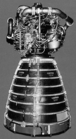
The first use of liquid propellant dates back to 1926, the rocket pioneering days of Robert Goddard.[5]In the 1940s this was followed by the illustrious V-2, also known as the A-4, designed by Werner Von Braun and his team, which clearly demonstrated the high performance capability of liquid propellant rocket propulsion systems. This was followed, in 1957, by the first true space launch when the Soviets launched Sputnik I. This event spurred a surge in rocketry in the United States that culminated in 1969 with the first manned lunar landing, made possible by the design and development of the powerful Saturn V all liquid propellant rocket system. Today, liquid propellant propulsion systems launch most rockets for crewed spacecraft, so allowing humanity to expand its presence into space. Typical examples are Ariane 5 core stages, the Space Shuttle main engines (Figure 9.9), and the Cassini, Galileo, and NEAR spacecraft.
An important distinction for liquid rockets is in regards to application. We distinguish between launcher propulsion and spacecraft propulsion . The prime focus for launcher propulsion is to achieve a high thrust (to overcome gravitational acceleration) and a high specific impulse to reduce propellant mass. For space launchers, because of the short thrust duration and because of the limited importance of short launch preparation time, cryogenic propellants may be used. For spacecraft propulsion, the focus is on storable and hypergolic propellants (i.e. propellants that “explode” when coming into contact with each other) to attain high reliability and a longer mission life.
9.3.2.3 Hybrid Rocket
In a hybrid rocket motor the oxidizer and fuel are stored in different physical states. In most cases, a solid fuel is stored in the combustion chamber into which a liquid or gaseous oxidizer is injected. The solid fuel is stored in the shape of a shaped block referred to as the fuel grain. The liquid oxidizer is either stored at room temperature or at very low (cryogenic) temperatures in a storage tank. Pressurized gas is used to feed the liquid into the combustor, gas generator or pump. To start motor operation, an ignition device is needed. After full combustion is accomplished, the motor burns until the oxidizer flow is halted, and the motor shuts down.
The first investigations into hybrid rocket propulsion took place in the 1930s. It was the former USSR that first flight-tested a hybrid rocket motor, reaching an altitude of 1500 m. In this test motor, liquid oxygen was used as oxidizer and colloidal benzene as fuel. At the same time, the Germans tested a hybrid rocket motor using laughing gas (N2O) as oxidizer and coal as fuel. In the 1960s, ONERA in France developed a hybrid sounding rocket using amine fuel and nitric acid oxidizer. At the same time, United Technologies (USA) developed a high-altitude supersonic target (HAST) drone using a polybutadiene fuel and nitric acid oxidizer. HAST flew for the first time in 1969. It demonstrated a range greater than 150 km. In the 1980s and early 1990s AMROC (USA) designed and hot test fired a wide variety of hybrid rocket motors of all sizes, utilizing non-toxic, storable propellants.
To date, only few applications have been found for hybrid rocket engines. One of the reasons is that during the 1960s solid rocket systems were studied in depth for military purposes. This resulted in a large amount of knowledge on solid propellants and how they burn. Hybrid rocket motors are sometimes used for drones, meteorological rockets and educational purposes. The motor developed by James Benson’s company for Burt Rutan, that uses neoprene as the propellant source and nitrous oxide as the oxidizer, is a unique rocket engine design in that a “throttle” can be applied to the propulsion system; it can shut down in emergency situations. This safety feature developed for Space Ship One and Two is of great interest to the space tourism industry. The problem with this propulsion system is that the noxious gases released are much more toxic than the exhausts of conventional liquid fuel systems.
9.3.2.4 Cold Gas System
Cold gas systems use an inert cold gas as the propellant. In addition to the propellant, cold gas systems consist of one or more engines, a propellant storage tank, sometimes a gage, and tubing. Any gas may be used as a propellant; nitrogen and helium are generally used. This is because these gases are highly inert and have low molecular mass. Helium offers the advantage that its specific impulse is about 2.5 times higher than that for nitrogen, giving a significant reduction in propellant mass, but at the expense of an increased storage volume or a pressure about seven times higher, plus a higher cost. The thruster essentially consists of a nozzle and a valve; the nozzle accelerates the cold gas to a high velocity, whereas the valve regulates the thrust generation and on/off switching. The energy required for propulsion is fully contained in the pressurized gas; no heating is needed. Cold gas systems were used on many early spacecraft as attitude control systems. Today, these systems are mostly used in cases requiring a low total impulse, or where extremely fine pointing accuracy or thrust levels must be achieved, or when the use of chemical propellants is prohibited for safety reasons.
9.3.3 Non-Chemical Rocket Propulsion
Non-chemical thermal rockets use separate power and energy sources to heat up a working fluid to a high temperature, after which the working fluid (i.e. the propellant) is discharged through a nozzle. Based on the type of heat or energy source used, we distinguish three types of non-chemical thermal rockets.
- Electro-Thermal Rocket Systems. These systems use electrical energy to heat a propellant, which is then discharged through a nozzle. Heating can be accomplished by resistance heating or by an arc discharge. Such systems use either an external energy source like the Sun, or an internal energy source like a nuclear fusion reactor or a radioisotope generator.
- Nuclear-Thermal Rockets. These rockets use the heat produced by a nuclear reactor to heat the propellant, using either a solid heat exchanger or particulate absorption.
- Laser-Thermal and Solar-Thermal Rockets. These systems use laser energy or solar energy to drive a heat exchanger, which then heats the expellant. Because the heating is direct, no losses occur due to the conversion of thermal energy into electrical energy, and so the thrust levels are higher than for electro-thermal rockets.
9.4 So, what does it do? The Payload
Earlier, we learned to think of a spacecraft as collections of subsystems, each of which has a specific task, working together to perform a specified mission. Each of the subsystems introduced previously does not perform the tasks that directly result in completing a mission’s objectives, but they perform tasks to maintain and monitor the spacecraft they provide the spacecraft with a frame, or with power, or allow it to navigate properly. The collection of the subsystems that support the spacecraft is referred to the spacecraft bus. Each spacecraft consists of a spacecraft bus as well as one more subsystem: the payload.
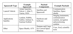
The payload subsystem consists of all the tools in the spacecraft that directly achieve the objectives of its mission. This definition is very broad when we consider the wide range of objectives that space missions can have. For example, there is the payload of an Earth observation satellite, which might consist of photographic, radar or multi-spectral instruments to image the Earth. This is quite different from the payload of, say, the Euro-pean Space Agency’s Automated Transfer Vehicle (ATV), which consists of cargo that is to be delivered to the International Space Station, or the waste materials removed from the space station; as it descends from orbit it burns up in the Earth’s atmosphere. In general terms, we can group different payloads into one of three categories, as shown in Table 9.3.
With all the various types of payloads, it can be difficult to choose what the best payload is to use for any mission – that is one of the key tasks of a spacecraft designer. The wide range of payload options is greatly reduced by the objectives and constraints of the mission. There are only a handful of payloads that can perform a task such as observing the Earth in the visible range of light. First, a spacecraft designer must analyze all the mission objectives and constraints to determine all the possible payloads that would work. Then the designer examines several aspects of the payload to figure out which best meets the mission objectives, at the lowest cost, and yet entails the lowest acceptable risk of failure.
Because of the high cost of launching objects into space, one of the most critical factors in choosing a payload is ensuring that it is as light as possible. As the mass of the payload increases, the mass of the structural subsystem that supports it also increases, which greatly increases the overall mass of the spacecraft. This example shows that choosing the best pay-load not only depends on the characteristics of the payload itself, but also on the payload’s effect on the spacecraft bus.
In some cases, a smaller payload may need more power. The designer must consider how much power the payload requires, and its impact on mass and risk factors. As the amount of power that a payload requires increases, the mass of the power subsystem has to increase, leading to a more massive satellite. That leads to higher costs, not only to construct and test the satellite but also to launch it as well.
9.5 Robots in Space – Payloads that do Real Work
The word robot comes from the word robota meaning serf labor, or hard work, in Slavic languages (Czech, Slovak and Polish), and was introduced to the public by Czech writer Karel Čapek in his play R.U.R. (Rossum’s Universal Robots), premiered in 1920. In the play, the robots are described as artificial creatures, or androids that can be mistaken for humans.
Today, the word robot is used for a mechanical, or artificial, agent that can behave interactively with environments or humans in some coordinated ways. A humanoid , a human looking robot, attracts the public attention, though the robots used in industry are automated or programmable handling devices, which do not look much like humans. Industrial robots are successfully working on the mass production lines of industrial factories, conducting repetitive tasks such as welding or assembling motor vehicles. But most research efforts are now put into robots to work outside the factory , such as in offices, homes and hospitals, or in fields, or even inside human bodies (nano-robots), or in outer space. Robotics is a discipline of system integration making the most of our knowledge of many different disciplines, including mechanics, electronics, computer technology, bioengineering, and even anthropology and sociology.
Artificial Intelligence (AI) is one major aspect of a robot, but not all of it. Physical motion control is an indispensable basis in many cases. For the robots that function in the real world, intelligence means an ability to negotiate (or perform appropriate behaviors) in the physical environment, but not merely mental or psychological ability. For example, dexterous manipulation is achieved by a good combination of sensing (such as vision, or force or tactile sensing) and the motion control of the arms, hands, and fingers, under the coordination of the brain for perception, recognition, planning and execution. From a roboticist’s viewpoint, the instinct of primitive animals is the first level of AI that we should implement in an intelligent robot, even though the instinct was previously con-sidered to be opposite concept of intelligence.
Autonomy is another aspect of the robot. Any unmanned spacecraft that is under an automated control sequence may be referred to as a robotic satellite. However, when we use the term Space Robot it means a more capable mechanical system that can facilitate manipulation, assembling, or servicing tasks in orbit, to assist astronauts. In time space robots may become more capable and able to explore remote planets as surrogates for human explorers. The most advanced concept we now have of a space robot is what is called a von Neumann Machine . This is a robotic device that could go to another planet, create a processing plant, replicate itself and send additional probes to explore even further out into the cosmos. In theory, a von Neumann Machine could not only reproduce itself multiple times but could even improve on its original design. This would demonstrate a “thinking” mechanism.
Key issues in space robotics are characterized as follows:
Manipulation --Although manipulation is a basic technology in robotics, microgravity in the orbital environment requires special attention to the motion dynamics of the manipulator arms and the objects being handled. Reaction dynamics, that affect the base body, impact dynamics when the robotic hand contacts an object to be handled, and vibration dynamics due to structural flexibility are included in this issue.
Mobility --The ability of locomotion is particularly important in exploration robots (rovers) that travel on the surface of a moon or a remote planet. These natural surfaces can be rough, and thus challenging to traverse. The robotic technologies of sensing and perception, traction mechanics, and vehicle dynamics, control and navigation must first be demonstrated in a natural untouched environment on Earth.
Tele-Operation vs. Autonomy -- There can be a significant time delay between a robotic system at a remote worksite in space and the human operator in a control room on the Earth. In earlier orbital robotics demonstrations, the tele-operation delay (termed latency) was typically only a few seconds, such as for a mission on the Moon. But the delays could be several tens of minutes, or even hours for planetary missions. Tele-robotics technology is therefore an indispensable ingredient in space exploration, and the introduction of some autonomy is a reasonable consequence of such protracted transmission delays.
Extreme Environments -- In addition to a microgravity environment that affects the motion dynamics of the robots, there are many other issues related to extreme space environments that are challenging. They must be solved in order to enable practical engineering applications. Such issues include extremely high or low temperatures, high vacuum or high pressure, corrosive atmospheres, ionizing radiation, and very fine dust.
Versatility -- The ultimate space robot would be not only autonomous but also versatile, doing all the tasks by itself using its own resources. There have been communications satellites designed with autonomous control that function close to this goal. A space robot, therefore, should be versatile in such extreme space environments as mentioned before, and versatile with regard to many different situations and scenarios that it might encounter. The ultimate versatility would be the so-called von Neumann machine described above.
9.5.1 Orbital Robotic Systems: Past and Present
The first robotic manipulator arm used in the orbital environment is the Space Shuttle Remote Manipulator System, a.k.a., the “Canadarm,” designed and built in Canada. Successfully demonstrated on the STS-2 mission in 1981, it is still operational today. This success opened a new era of orbital robotics and inspired a number of mission concepts in the research community. A long-term goal that has been discussed intensively since the early 1980s is to rescue and service malfunctioning spacecraft using a robotic free-flyer or free-flying space robot. Later, manned service missions were conducted for the capture-repair-deploy procedure of malfunctioning satellites (ANIK-B, Intelsat 6, for example) and for the maintenance of the Hubble Space Telescope (STS-61, 82, 103 and 109). For all the above examples, the Space Shuttle, a manned spacecraft with dedicated maneuverability, was used. However, unmanned servicing missions have not yet become operational. Although there were several demonstration flights, such as the ETS-VII of Japan and the Orbital Express, an experiment of the US Defense Advanced Research Projects Agency (DARPA), the practical technologies for unmanned satellite servicing missions await the outcomes of future tests and experiments.
9.5.1.1 Space Shuttle Remote Manipulator System
The Canadarm is a mechanical arm that maneuvers a payload from the payload bay of the Space Shuttle orbiter. It can also grapple a free-flying payload and maneuver it to the payload bay. The Canadarm has been employed more than 100 times to deploy or retrieve payloads as well as assist human extra vehicular activities (EVAs), better known as “space walks”. Servicing and maintenance missions to the Hubble Space Telescope, and construction tasks of the International Space Station, have also been successfully carried out by the Canadarm in conjunction with humans on EVAs. As noted in the “story” told by Astronaut Jeff Hoffman earlier, the repair of the Hubble would not been possible without this capability. The Canadarm is pictured in Figures 3.1-3.3.
9.5.1.2 ISS mounted manipulator system
The International Space Station (ISS) is the largest international technology project ever, with 15 countries making significant cooperative contributions. The ISS is an outpost of the human species in space, as well as an orbiting laboratory with substantial facilities for science and engineering research. To facilitate various activities on the station, there are several robotic systems that often work in tandem. The Space Station Remote Manipulator System (SSRMS), Canadarm 2, shown in Figure 9.10, was launched into space in 2001 during STS-100. The Canadarm 2 has played a key role in the construction and maintenance of the ISS both by assisting astronauts during EVAs and using the SRMS on the Space Shuttle to hand over a payload from a Shuttle to the SSRMS.
The Special Purpose Dexterous Manipulator (SPDM), or Dextre, which was attached at the end of the SSRM in 2008 by STS-123 (ISS assembly flight 1J/A), is a capable mini-arm system to facilitate the delicate assembly tasks currently handled by astronauts during EVAs. Dextre is a dual arm manipulator system, where each manipulator having seven degrees of freedom is mounted on a one degree-of-freedom body joint. Each arm has a special tool mechanism. The arms are tele-operated from inside the ISS. The European Space Agency (ESA) is also providing a robotic manipulator system for the ISS, the European Robotic Arm (ERA), which will be used mainly to work on the Russian segments of the station.
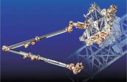
In Japan, the Japan Space Exploration Agency (JAXA) has developed the Japanese Experiment Module Remote Manipulator System (JEMRMS), shown in Figure 9.11. The arm will be attached to the Japanese module of the ISS. After installation, the arm will be used to handle and relocate the components for the experiments and observations on the Exposed Facility.
9.5.1.3 ETS-VII: “Orihime” and “Hikoboshi”
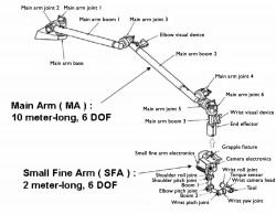
The Japanese Engineering Test Satellite VII was another historical milestone in the development of robotics technology in space, particularly in the area of satellite servicing. ETS-VII was an unmanned spacecraft developed and launched in November 1997 by the National Space Development Agency of Japan (NASDA), now named the Japanese Aerospace eXploration Agency (JAXA). Several experiments were successfully conducted using a two-meter-long, six-degree-of-freedom manipulator arm mounted on its carrier satellite.
The mission objective of ETS-VII was to test free-flying robotics technology and to demonstrate its utility in unmanned orbital operation and servicing tasks. The mission consisted of an autonomous rendezvous/docking and a number of robot experiments. For the rendezvous experiments, the spacecraft was separated into two sub-satellites in orbit, one is named “Orihime” and behaved as a target, and the other is named “Hikoboshi” and behaved as a chaser. The meaning of these names in ancient mythology was mentioned in Chapter 2. The robot experiments included a number of tasks that included testing of tele-robotic operations with up to a seven-seconds transmission delay, and a simulated refueling of a satellite.[6],[7]
9.5.1.4 Orbital Express
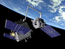
The Orbital Express Space Operations Architecture program is a US Defense Advanced Research Programs Agency (DARPA) program developed to validate the technical feasibility of robotic on-orbit refueling and reconfiguration of satellites, as well as autonomous rendezvous, docking, and manipulator berthing. The system consists of the Autonomous Space Transport Robotic Operations (ASTRO) vehicle, developed by Boeing Integrated Defense Systems, and a prototype modular next-generation serviceable satellite, NextSat, developed by Ball Aerospace. The ASTRO vehicle is equipped with a robotic arm to perform satellite capture and fuel exchange operations, as illustrated in Figure 9.12.
After the launch of the Orbital Express in March 2007, various mission scenarios were conducted, including visual inspection, fuel transfer, fly-around, rendezvous, and docking with NextSat. These scenarios were successfully completed by July 2007, with ASTRO’s onboard autonomy robot employing the onboard cameras and advanced video guidance system.
9.5.2 Surface Robotic Systems: Past and Present
Research on surface exploration rovers began in the mid-1960s, with an initiative for an un-manned rover for the Surveyor lunar landers and a manned rover (“moon buggy” ) for the US human missions on the Moon. During the same period, research and development began for a teleoperated rover named Lunokhod in the Soviet Union. Both the Apollo manned rover and the Lunokhod unmanned rover were successfully demonstrated in early 1970s.[8]In the 1990s the exploration target had expanded to Mars; in 1997, the Mars Pathfinder Mission successfully deployed a micro-rover named Sojourner that safely traversed the rocky field adjacent to the landing site by autonomously avoiding obstacles.[9]Following up on this success, today, autonomous robotic vehicles are considered indispensable technology for planetary exploration. The Mars Exploration Rovers, Sprit and Opportunity , launched in 2003, have had remarkable successes, remaining operational in the harsh environment of Mars for over three years. Each has traveled more than 7.5 km, and has made significant scientific discoveries using on-board instruments.[10]
9.5.2.1 Lunokhod
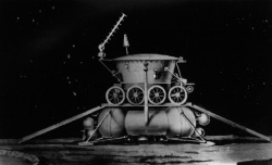
The first remotely-operated robotic space surface vehicle was Lunokhod, a drawing of which is shown in Figure 9.13. Lunokhod 1 landed on the Moon on November 17, 1970 as a payload on the lander Luna-17, and Lunokhod 2 landed on the Moon on January 16, 1973. Both were 8-wheeled vehicles having a mass of about 840 kg. Almost all components were in a pressurized thermal enclosure. The Lunokhod looked like a bathtub , with a lid that closed over the tub. With the temperature on the surface of the Moon reaching around 120 degrees Celsius during the daytime and -170 Celsius degrees during the lunar night, the day and night each lasting 14 Earth days, it was a challenge to design a robot that could survive both the extreme heat and cold. The design of the bathtub and lid aided the thermal protection of the vehicle’s controls. On the lid were solar arrays that recharged batteries during the day.
Lunokhods were remotely driven by a driving team in the U.S.S.R., consisting of a driver, a navigator, a lead engineer, an operator of a communication antenna, and a crew commander. There was approximately three seconds of delay with commands and return signals traveling at the speed of light. The driver viewed a monoscopic television image from the vehicle, and gave the appropriate commands such as “turn”, “proceed”, “stop”, or “back up”. The vehicles had both gyroscope and accelerometer-based tilt sensors that could automatically stop the vehicle in the event of excessive tilt of the chassis. Typical mobility commands specified a time for which the motors would run, and then stop. Precision turning commands specified the angle through which the vehicle was to turn. A ninth small wheel, that was un-powered and lightly loaded, determined the distance covered. Lunokhod 1 successfully operated for 322 Earth days. It traversed over 10.5 km during that period, and returned over 20,000 TV images and 200 high-resolution panoramas. It provided the results of more than 500 soil penetrometer tests and 25 soil analyses using its X-ray fluorescence spectrometer. Lunokhod 2 operated for about 4 months. It traversed more than 37 km before the mission officially terminated on June 4, 1973. Lunokhod 2 was lost prematurely when it began sliding down a crater slope.
9.5.2.2 Apollo Lunar Rover
The Lunar Roving Vehicle (LRV), Moon Buggy was an electrically powered surface exploration vehicle deployed during the Apollo program so that the astronauts could extend their range of surface extravehicular activities. Three of the Apollo missions brought LRVs to the moon, namely Apollo 15, 16 and 17. A summary of the distances traveled by the various Moon Buggy missions is listed in Table 9.4.
9.5.2.3 Mars Rovers – Sojourner, Spirit, Opportunity and Curiosity
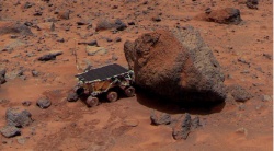
The first successful Mars rover was Sojourner , shown in Figure 9.14, was part of the NASA Mars Pathfinder Mission launched on December 4, 1996. After a 7-month voyage it landed on Ares Vallis, in a region called Chryse Planitia on Mars, on 4 July 1997. The Sojourner rover was then deployed from the lander to execute many experiments on the Martian surface.
The Mars Pathfinder mission carried a series of scientific instruments to analyze the Martian atmosphere, climate, geology and the composition of its rocks and soil. It was a project from NASA’s Discovery Program, which promotes the use of low-cost spacecraft and frequent launches under the motto “cheaper, faster and better.” The goal of the mission was regarded as a “proof-of-concept” for various technologies, such as airbag-assisted touchdown and automated obstacle avoidance, both later exploited by the Mars Exploration Rovers.
For rough terrain mobility, a unique suspension arrangement called the Rocker-Bogie system was developed. The term “rocker” comes from the design of the differential, which keeps the rover body balanced, enabling it to “rock” up or down depending on the various positions of the multiple wheels. The term “bogie”, on the other hand, comes from the old railroad systems, and refers to the train undercarriage with six wheels that can swivel to curve along a track. The Rocker-Bogie is a suspension system that connects six wheels using a passive linkage mechanism, performing as a type of a mechanical equalizer. Thanks to this the rover can go over a rock obstacle larger than the diameter of the wheel.
The Sojourner rover had a semi-autonomous navigation capability, which was successfully demonstrated during the remote operation under the communication round-trip delay of 10 to 15 minutes during the mission.
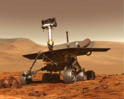
NASA’s Mars Exploration Rover (MER) Missions landed two rovers — Spirit and Opportunity — to explore the Martian surface and geology. The MER-A rover, Spirit, was launched on June 10, 2003, and MER-B, Opportunity , on July 7, 2003 (see Figure 9.15). Spirit landed in Gusev crater on January 4, 2004; Opportunity landed in the Meridiani Planum on the opposite side of Mars from Spirit, on January 25, 2004. The hardware design concept of these twin rovers follows that of the Mars Pathfinder mission which was successful in 1997, but with larger rovers. The Sojourner was about the size of a microwave oven, but the Sprit and Opportunity are about the size of a golf cart. The recent rovers used an air-bag system for landing and a six-wheel system with Rocker-Bogie suspensions. They have on board stereo cameras and hazard cameras for long-range navigation, and a manipu-lator arm for scientific operations. At the end tip of the arm are a number of instruments to perform scientific investigations on the rock and soil targets of interest. The total distance traveled by the two rovers is more 19 km, as of sol 1524 (April 16, 2008; Spirit’s total odometry remained at 7,528 meters and as of sol 1497 (April 9, 2008), Opportunity’s total odometry was 11,689 meters).
In 2012, NASA landed its most ambitious robotic rover to date - a 899 kg, nuclear powered rover the size of a small automobile. Curiosity’s exploration of Gale crater and Mount Sharp was focused on investigating the Martian climate and geology, and investigating environmental conditions favorable to the microbial life. The mission utilized a unique “sky crane” landing system that lowered the rover on the Martian surface using an overhead propulsion system that was expended after the rover’s landing. Curiosity is powered by a radioisotope power source that produces heat and electricity via the decay of radioactive plutonium-239. Similar power systems have enabled multi-decade mission lifetimes, powering missions such as Pioneer, Voyager, Viking and Cassini.
9.6 Keeping in Touch – Ground and Mission Operation
Having introduced the various subsystems that make up a spacecraft and the different types of payloads, a designer knows the capabilities and requirements of the subsystems and payloads to meet a particular mission’s objectives; however, there is one more aspect of a space mission that greatly affects its chances for success as well as its overall costs. This missing aspect is referred to as “mission operations.” This is not a physical component of the spacecraft, but the collection of activities and tasks involved with controlling and operating the spacecraft.
The people who focus on mission operations are called “mission operators;” their activities begin once the spacecraft is launched. These activities include such tasks as controlling the spacecraft, monitoring the spacecraft’s health and processing the data gathered during the mission. If the mission involves a crew, mission operators must also monitor the health and plan the activities of the crew. Mission operators not only need to determine what operations must be done, but also when the operations must occur. Improper scheduling of operations can lead to increased costs and complexity as well as affecting the likelihood of a successful mission.
During the mission, there are several different aspects of a mission on which operators must focus. One of their key jobs is to perform the duties of “mission control”. These members of the team focus on the daily activities of the spacecraft that are necessary to achieve the mission. These are usually laid out in the Mission Operations Plan, but there are oftentimes when the operation of the spacecraft requires real-time decision making because of an unforeseen incident. The operators may need to receive data from the spacecraft’s instruments before developing the appropriate plan.
For the mission control team to perform its duties, there are several other teams that work together. There is always a team in charge of monitoring the health and performance of the spacecraft bus and passing that information on to mission control. Similarly, the health and performance of the payload is monitored to ensure that it is working according to plan. Another team focuses on ensuring that the positioning and navigation of the spacecraft is performing as required. If one of the payloads is a human crew, there will also be a team focusing on their health and activities. The final area where a supporting team is required is to deal with communications with the spacecraft. All these teams work together to ensure that the mission is achieved as smoothly and successfully as possible.
The number of people required to form these teams can vary greatly. The number of operators can be either a few individuals or a large team depending on the complexity of the mission. For very complex missions, each area can have its own team or, for simple missions, several areas can be the responsibility of a single person. The members of the mission operations team are housed in facilities called “mission control centers.” Linked to a mission control center is a ground system which houses all the electronics and antennas required to communicate with the satellite. The location and number of ground stations depends on several factors, one of which is how often the mission operators need to be in communication with the spacecraft. For any communication, the ground station antenna must be in line-of-sight to the spacecraft. If operators require constant communications with the spacecraft, they will need to have ground stations spaced around the globe to ensure that at least one antenna can always “see” the spacecraft.
Mission Control Centers are generally rather large and expensive installations, not only because of their size, the equipment involved and the 24-hour a day staffing, but also because of their redundant communications links to ground control facilities. For deep space installations, these centers are positioned around the world so as to receive signals continuously as the Earth rotates on its axis. For example, the European Space Agency maintains a facility for ground tracking, telemetry, control and command center located in Kiruna, Sweden.
9.7 Mission Design – Putting all the Pieces Together
Space mission design involves the integrated knowledge of payloads, spacecraft, launch vehicles, orbital mechanics, communications, and operations infrastructure. Mission design brings together these variables to create a consistent, end-to-end (pre-launch to payload disposal) space mission. A successful mission design can be measured by the accomplishment of all the mission-level requirements within the mission constraints.
The designs of human and robotic missions have both similarities and differences. Crewed missions require human-rated launch vehicles, trajectories with abort options, and additional subsystems to sustain a crew’s health and productivity, and require more reliable systems than robotic missions. Generally, robotic missions are designed with cost and science performance as the limiting metrics. Human missions are generally designed with risk reduction as the prime metric.
Mission design can be thought of as a process that begins with defining a mission statement, objectives and constraints, continuing with brainstorming options for the mission’s “building blocks” and logically combines these pieces into different mission design alternatives, and concluding with the evaluation of mission design options and the down-selection of a preferred mission design alternative based upon multiple metrics and achievement of the original requirements.
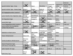
Many mission design options are possible because there are so many combinations of “building block” variables. It would be impossible to examine all the mission design options so we first attempt to reduce the number of viable mission design paths by eliminating options that violate the laws of physics, or are logically disconnected. Following that, other options can be eliminated based upon technical analysis (for example, an option may be prohibitively massive) or for non-technical constraints (such as being too costly). Table 9.5 illustrates an example mission option menu, with de-selected options crossed out, and selected options highlighted.
Once the designer has reduced the number of mission options, the mission design process becomes an exercise in producing performance, risk and cost metrics with which to compare the many mission options. A first-order analysis that produces only performance (mass) estimates is usually sufficient to further down-select the number of mission options, since to first order cost and mass are linearly related. After eliminating those options that are much more massive than other options, the designer typically assesses the relative risk and cost of each remaining option. A combination of performance, cost and risk, (but not necessarily the optimum solution in any one of these three areas) will ultimately decide the mission design chosen.
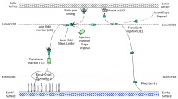
Mission designers often illustrate their mission using graphics such as “bat charts”. For an example lunar mission, the bat chart shown in Figure 9.16 begins with the Earth launch of the mission elements at the bottom left and the mission timeline proceeds from left to right. Note that the destination (in this case, the moon) is at the top of the diagram, and that the lander hangs like a bat from the lunar surface when it lands.
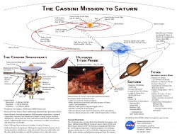
Figures 9.17 illustrates a complex mission design – the Cassini/Huygens robotic science mission to Saturn – and illustrates multiple spacecraft, complex astrodynamics, and complex mission design for this highly successful science mission.
9.8 Assembling a Space Program
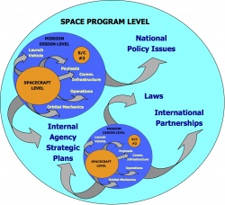
The term “Space Program” invokes images of large undertakings such as the Apollo moon landings, the International Space Station, or flotillas of robotic spacecraft bound for a planet. At this highest level of the 3-level model, shown in Figure 9.18, multiple space missions become integrated with the internal Strategic Plans of various Space Agencies, Policy Issues of different Nations, International Space Law, International Partnership Agreements, and commercial forces. A space program “architecture” thereby consists of the topmost structure, arrangement, or configuration of system elements and relationships required to address both technical and national (and often international) factors. Creating the space program level requires a specialized skill set that combines an understanding of engineering, politics, business and law. The ultimate “owner” of a space program is often a space agency Administrator, Minister of Space or high-ranking Space Program “Architect”. This individual is responsible for the highest level of integration within the sphere of space activities, and has often arrived at this position through many years of experience.
An excellent (but ultimately unrealized) example of a space program architecture was one proposed in 1964 by Wernher von Braun. Von Braun was a prominent figure in the development of NASA’s Apollo program, but he saw Apollo as only the first step in a much longer-rang program to build space shuttles, orbiting space stations, large, inhabited lunar bases and elaborate human Mars missions. And while these will all eventually become reality, von Braun envisioned his program achieving all these goals by 1989. Figure 9.19 shows the entire von Braun architecture, from initial steps on the moon through hundreds of “men” living on Mars, the moon or in Earth orbit within two decades. Von Braun’s original plans for shuttles and Earth orbiting stations were bypassed when the U.S. decided to go directly to the moon in the 1960’s. Following the end of the Apollo program, the United States did eventually return to the initial steps of von Braun’s plan by developing a space shuttle, and an Earth-orbiting station.
9.8 Successfully Designing Systems to Go Into Space
In the previous two chapters, we have learned a great deal about how and why to design spacecraft. We have learned about both the supporting spacecraft “buses” as well as the prime payload. The design of these systems is challenging, involving a great deal of technology and management skills. Good communications are vital to the success of space programs—and we mean communications at all levels. There must be communications regarding requirements related to all of the subsystems, and how they support the overall mission and the payload design. There must be good communications regarding how the launch system, and the orientation and control thrusters, are compatible with and adequately support the mission objectives. There is a need to communicate accurately as to when a satellite can operate remotely as a robot and when a human crew is required. There must be clear communications as to what the mission objectives are in terms of schedule, acceptable risk, program budget and whether existing or new technology must be applied to the program. There is also need to communicate as to whether international cooperation is appropriate and what degree of public-private partnership might be required. In the design of launch systems[11], there must be careful communications as to what type of rockets or propulsion system is needed and for what tasks. Many and, in fact, most space programs that ultimately fail probably break down due to communications failures. It is our hope that we have managed to communicate, at least to some reasonable degree: “Why and How We Go to Space.”
Footnotes
- ^ J. Wertz and W. Larson, Space Mission Analysis and Design, 3rd edition, Microcosm, 1999
- ^ R. R. Bate, D. D. Mueller and J. E. White, Fundamentals of Astrodynamics, Dover, 1971
- ^ G. P. Sutton and Oscar Bilbraz, Rocket Propulsion Elements, 7th Edition, Wiley, 2001
- ^ R. W. Humble, G. N. Henry, and W. J. Larson, Space Propulsion Analysis and Design, McGraw-Hill, 1995
- ^ D. K. Huzel and D. H. Huang, Design of Liquid Propellant Rocket Engines, Revised Edition, AIAA, 1992
- ^ M. Oda et al, “ETS-VII, Space Robot In-Orbit Experiment Satellite,” Proc. 1996 IEEE Int. Conf. on Robotics and Automation, pp.739–744, 1996
- ^ K. Yoshida, “Engineering Test Satellite VII Flight Experiments For Space Robot Dynamics and Control: Theories on Laboratory Test Beds Ten Years Ago, Now in Orbit,” International Journal of Robotics Research, Vol. 22, No. 5, pp. 321–335, 2003
- ^ “Lunokhod 1 Mobile Lunar Laboratory, USSR” published by the Joint Publications Research Service (JPRS identification number 54525.), US Department of Commerce, a translation of a Russian language monograph: Peredvizhnaya Laboratoriya na Lune Lunokhod-1, responsible Editor Academican A. P. Vinogradov, Moscow, 4 June 1971, 128 page
- ^ A. Mishkin, Sojourner: An Insider’s View of the Mars Pathfinder Mission, Berkley Books, 2004
- ^ M. Maimone, C.Y. Yang, L. Matthies, “Two years of Visual Odometry on the Mars Exploration Rovers,” Journal of Field Robotics, Vol. 24, No. 3, pp. 169–186, 2007
- ^ M. J. L. Turner, Rocket and spacecraft propulsion: Principles, practice and new developments, 3rd Edition, Springer-Praxis, 2009
The Farthest Shore – Chapter Ten Space Policy, Law and Security

